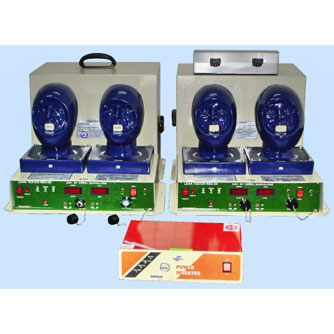
The leak tester essentially consists of two dummy heads and a suction generator which is connected to a needle valve and flow Meter. The flow meter outlet is connected at the mouth of the dummy Head. A pressure sensor located below the dummy head is also connected to the mouth through an adjacent steel pipe.
When the mask is not fitted on the dummy head, the flow display shows maximum inward flow and suction display shows zero. When mask is fitted, the leak flow rate decreases, the cavity suction level goes on increasing depending on the degree of fitment and tightness of the mask.
The tester is provided with digital display and a logic circuit which indicates within 40 seconds whether a mask has passed / failed. This facility simultaneously compares the test values with admissible values and a comparator network decides whether the masks satisfies the pass / fail criteria. The glowing of green LED indicates the mask has passed. In the event of failure, the reason is also indicated as, suction fail or Flow (leak rate) fails
by glowing of respective red LEDs.
The admissible values for suction and flow are engraved on the top of the panel for quick reference.
|
Dummy Head |
Made of F.R.P. in three sizes; small, medium & Large size. |
|
Suction Pump |
Max. Suction 20 inches WC. |
|
Flow Sensor |
100 to 1000 cc/min. Turbine Flow Sensor. |
|
Pressure Sensor |
0 to (-) 600 mm WC. Diaphragm type. |
|
Digital Indicator/Controller |
90 x 90 x 150 mm unit complete with input transformer, power supply board, set point, Set adjust, calibration/zero adjust knob, one set of relay potential free contacts on the rear side, and 3 ½ |
|
Operation |
230 VAC 50 Hz Mains |
|
Power Consumption |
110 VA. |
|
Fuse rating |
Total kit fuse 2A, 500 mA |
|
Line filter and spike buster |
Provided in the power cord connecting unit itself this eliminate EMI/RFI also protects from Lightning. |
|
Pass/fail indication |
By LEDs on front panel. |


